
Designed around the assembled demo—not a generic ESP32 case
The 44-pin YD/AITRIP controller plugs into its green terminal adapter, so clipping the ESP32 PCB itself would obstruct the header rows. The current first-fit model mounts the adapter through four board holes. Short M2.5 screws form a light thread in blind plastic pilot slots; no nuts or heat-set inserts are required for stationary bench use.
plain-plastic RF path
RF + wiring
gap
two bounded USB-C apertures
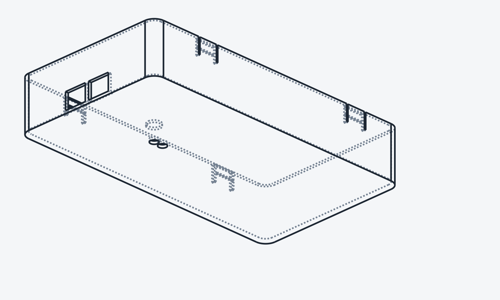
A clean, closed-side cover with bounded USB access
The separate inverted tray snaps around the existing printed carrier with four compliant side latches and a segmented edge groove. It uses no additional screws. Both long walls are closed. The short USB end retains its lower wall and a 2 mm center rib, with only two nominal 12 x 9 mm connector apertures centered at Y = -7 mm and Y = +7 mm. Their locations remain first-fit estimates relative to the provisional controller origin.
Two small top holes provide probe access to RST and BOOT. Their longitudinal positions come from the controller's 2.54 mm pin grid. The onboard RGB is covered by a 0.45 mm white-plastic membrane rather than a large opening. Control location, latch force, cable clearance, light diffusion, and RF performance remain physical-validation items.
Download the first-fit package
Start with the three small coupons. They turn printer and material tolerances into a cheap measurement before the full carrier and cover are printed.
Print → fit → prove
Calibrate cheaply
Measure the adapter-hole pattern, then print all three coupons in the intended material. Confirm the screw pilot, PN532 clip force, and cover latch before a full print.
Assemble openly
Print the flat carrier in PETG, mount the adapter with four M2.5 × 6 mm screws, then install the controller and PN532. Use a brim if the long corners begin lifting.
Test the real system
Finish internal wiring, disconnect USB, and snap on the roof-down cover. Insert the intended USB plug or plugs through the two bounded apertures; then verify probe access, RGB diffusion, bridge quality, and NFC read/write beside the printer.
What the computer proved—and what it did not
- Actual adapter hole pitch is measured
- Adapter seats on all four bosses
- Four screws start without splitting
- PN532 clips without visible stress
- Both USB-C plugs fit together
- Used terminals and BOOT/RST are reachable
- Cover snaps without whitening, cracking, or PCB contact
- Both bounded USB-C apertures align without loading the connectors
- The two short USB bridges print cleanly
- Closed walls do not trap or abrade internal wires
- RST/BOOT work through the tool holes
- RGB is visible through the 0.45 mm membrane
- NFC works with ESP32 off, on, and Wi-Fi active
- Range remains reliable beside the A1 mini
Compatibility boundary
This is a mechanical carrier for an external PN532/ESP32 reader. It does not make a stock Bambu AMS Lite understand an NFC standard by itself. The current ParaMat browser writer creates OpenSpool 1.0 JSON on compatible tags; the bridge then maps supported data toward the printer. OpenTag3D is a separate encoding, and no native Bambu compatibility is claimed here.
The external OpenSpool Mini enclosure targets different controller hardware and is not redistributed here. This model is new CadQuery geometry derived from published board envelopes and mounting dimensions.
Design method
Published dimensions established the first geometry; the product photograph resolved orientation and access; the controller's 2.54 mm pin grid located the cover controls; RF constraints kept metal-filled material away; parametric CAD preserved revision speed; and automated checks rejected obvious plate, spacing, and envelope errors. The physical print now supplies the evidence that a screen cannot: actual shrinkage, latch force, connector reach, LED diffusion, and read range.
Copyright © 2026 Sunnyday Technologies. Covered hardware design files are released under CERN-OHL-S-2.0, which permits commercial use subject to its source and notice obligations. Files and resulting products are provided as-is and without warranty. Power off before assembly, prevent shorts, keep metal and wiring away from the PN532 antenna, and validate fit and radio performance before use.